Integrated metro infrastructure intelligence

From repeatable screening
to defensible action.

AegisCrete develops one coordinated solution source that connects reduced-manpower routine screening, geolocated asset data, accountable engineering review, targeted diagnostics, representative asset pathways, preventive-maintenance governance, standards-compliant rehabilitation, knowledge transfer and lifecycle monitoring.

Evidence before prescription Function before product Validation before scale
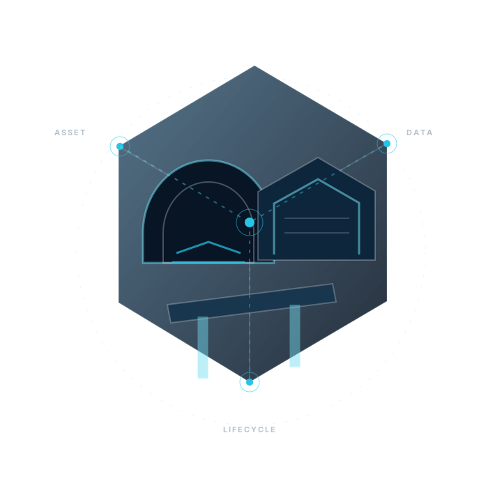
Abstract infrastructure network showing tunnel, station and viaduct assets connected to repeatable data capture, diagnostic decisions and lifecycle monitoring
01Screen
02Validate
03Decide
Scroll

Our position

An integrated point of responsibility and one coordinated solution source, not a universal product, a single sensor or an unsupported promise.

AegisCrete connects project context, asset, material and stewardship intelligence, specialist disciplines, digital data, controlled field delivery, verification and knowledge transfer into one traceable decision pathway. Different assets may require different platforms, methods, partners and solution categories.

“Select the technology for the diagnostic purpose—not the other way around.”

Construction history, material environment, operating constraints, diagnostic integrity, evidence maturity and client approval remain explicit decision gates.

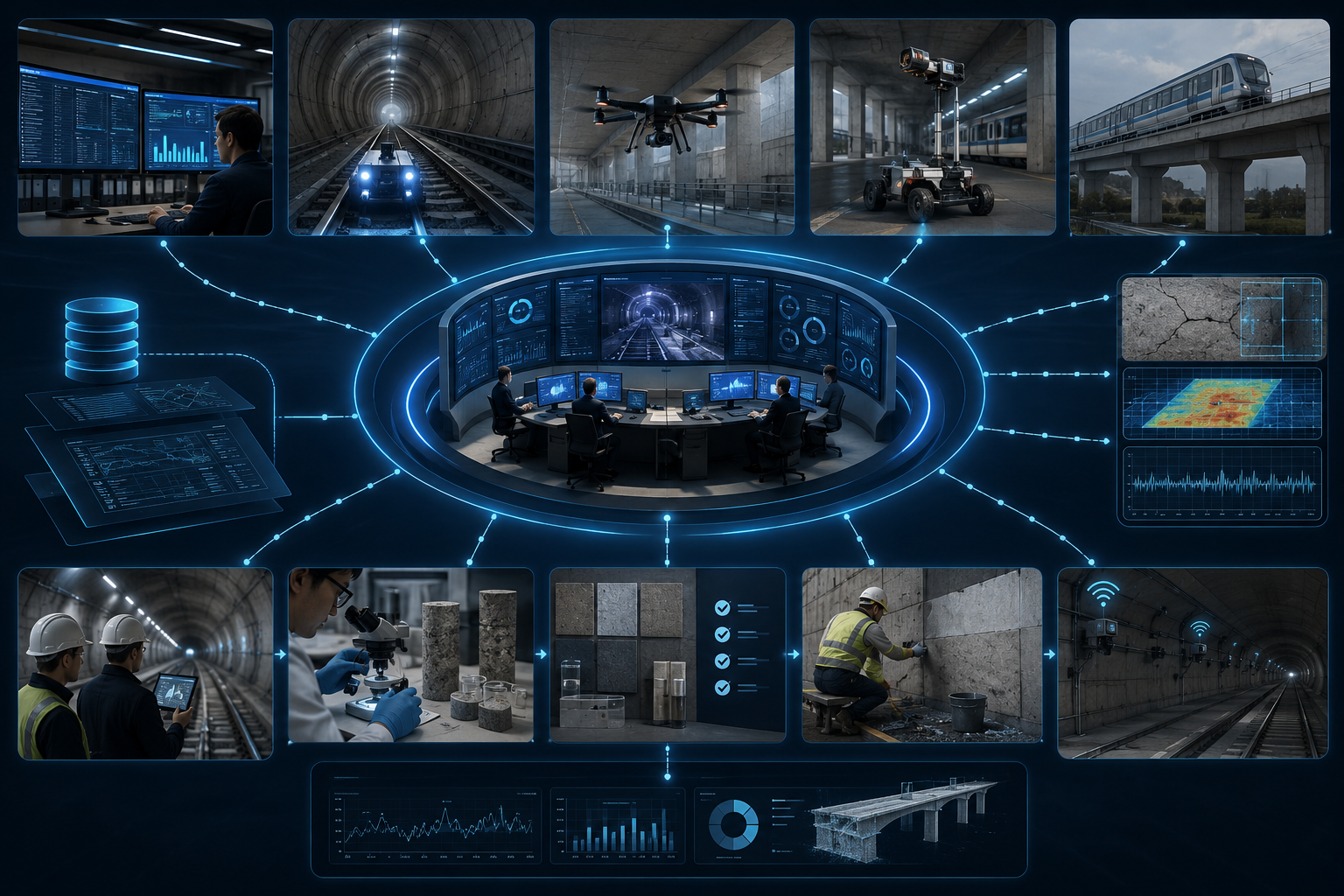
Integrated metro infrastructure coordination hub connected to inspection platforms, engineering validation, laboratory testing, controlled field work and lifecycle monitoring.
Integrated coordination across asset intelligence, inspection, validation, controlled delivery and lifecycle monitoring.

Integrated approach

One evidence chain.
Six accountable stages.

Each stage produces the information required to justify the next. Facts, assumptions and unknowns remain visible, and the pathway stops when the evidence is insufficient for a defensible selection.

  1. 01

    Asset, material and stewardship baseline

    Define the asset, section genealogy, construction method, material provenance, prior systems, repair history, operating knowledge, responsibilities and decision objective.

  2. 02

    Routine screening and capture

    Coordinate repeatable, geolocated visual, geometric and sensor data using mobile, fixed or specialist platforms appropriate to access conditions.

  3. 03

    Targeted diagnostic validation

    Test the questions that matter through touching-distance inspection, qualified NDT, calibration, ground truth, complementary methods and laboratory work where required.

  4. 04

    Eligibility and functional requirements

    Translate findings into required functions, candidate technology families, explicit exclusions, compatibility gates and evidence maturity.

  5. 05

    Controlled pilot and delivery

    Implement one representative use case through qualified resources, documented methods, railway-safety controls and measurable acceptance criteria.

  6. 06

    Verification, handover and lifecycle integration

    Confirm outcomes, preserve digital traceability, transfer procedures and decision rationale, monitor adjacent or recurring conditions and scale only after operational value is demonstrated.

Decision architecture

Two decision levels.
One controlled evidence chain.

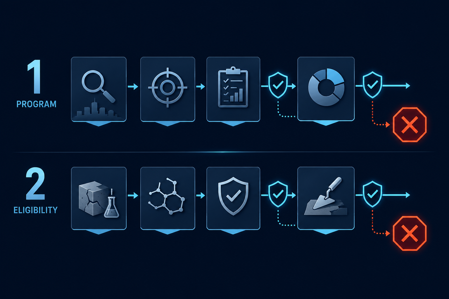
The framework separates program definition from detailed technology and solution eligibility. This allows useful scoping to proceed without pretending that incomplete data support a final prescription.

LEVEL 2

Material and solution eligibility

Determine what is technically admissible for a specific section.

Evaluate construction and material genealogy, existing systems, diagnostic confounders, compatibility, movement, vibration, exposure, maturity and approval dependencies.

STOP RULE

Evidence gate

Insufficient information produces an investigation plan—not a product answer.

When construction, material or validation data are missing, the framework identifies the missing evidence and the preliminary investigation required before final selection.

Controlled principle: a visible condition may define where to investigate, but it does not by itself establish the mechanism, the original source, the compatible repair chemistry or the correct long-term intervention.

Scope principle: the asset groups, conditions and technology pathways shown on this site are representative rather than exhaustive. Additional variables and disciplines may emerge from construction records, material provenance, operational history, stewardship knowledge and field evidence.

System-depth principle: many infrastructure conditions are volumetric and system-based rather than purely superficial. Where the decision requires it, surface observations should be complemented by subsurface, geometric, material, environmental and dynamic investigation.

Simplified two-level metro asset decision architecture showing program scoping, material and solution eligibility, evidence gates and stop rules.
Program scoping and material or solution eligibility remain separated by evidence gates and explicit stop rules.

Coordinated capability layers

A framework that connects disciplines,
technologies, field execution and accountability.

02

Automated routine inspection architecture

Rail-compatible, robotic, drone, terrestrial, telescopic or fixed platforms coordinated with repeatable routes, geolocation and suitable payloads.

03

Diagnostic integrity, coupled mechanisms and targeted NDT

Method selection by diagnostic question, with calibration, reference areas, ground truth, confounder control and qualified interpretation. Material, structural, environmental and operational variables are considered individually and in combination where their interaction may affect the condition or the diagnostic result.

04

Functional technology selection and exclusions

Candidate categories evaluated by required function, substrate condition, movement, cyclic loading, exposure, compatibility, maturity and approval pathway.

05

Rehabilitation, protection and controlled delivery

Water-path and drainage management, joints, localized reinstatement, corrosion control, coatings, steel and structural pathways implemented only where justified.

06

Digital traceability, knowledge transfer and lifecycle monitoring

Geolocated defect registers, repeat-image comparison, change detection, acceptance records, predictive-maintenance support, operating procedures, training, handover and maintenance integration.

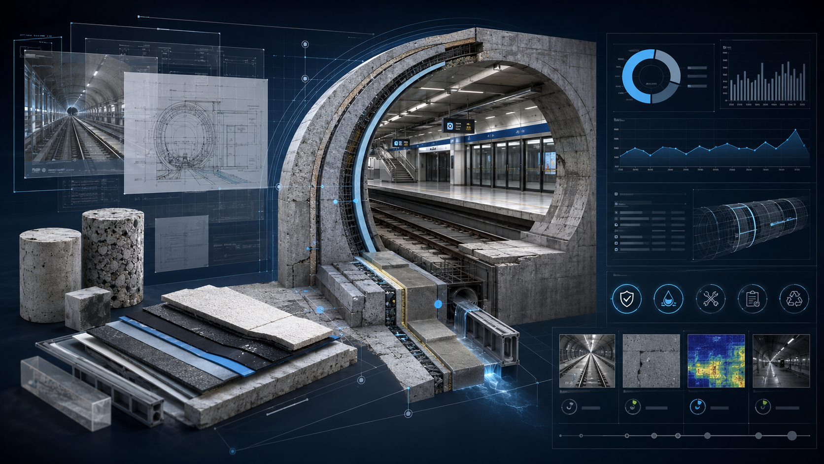
Conceptual metro infrastructure visual combining construction records, material samples, asset geometry, condition data and lifecycle stewardship intelligence.
CCL-01

Asset, material and stewardship intelligence

Asset, material and stewardship intelligence connected through one controlled evidence base.

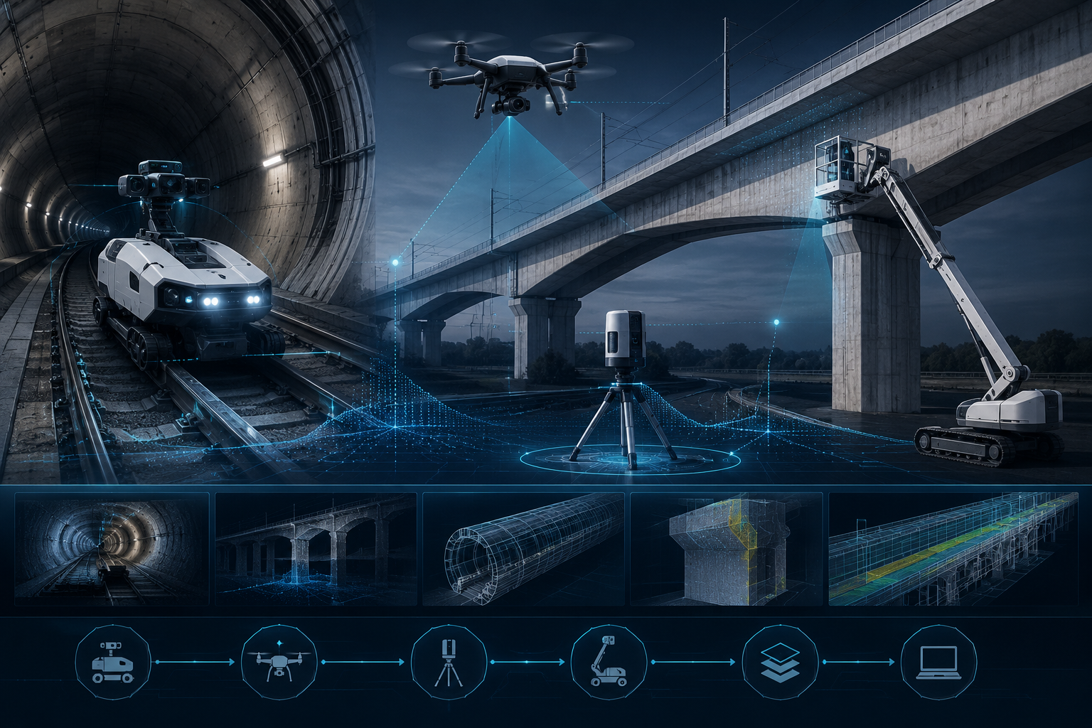
Conceptual automated metro inspection architecture using rail-compatible mobile capture, outdoor drone inspection, terrestrial LiDAR, high-reach access and geolocated data outputs.
CCL-02

Automated routine inspection architecture

Platform and payload combinations coordinated around repeatable, geolocated routine inspection.

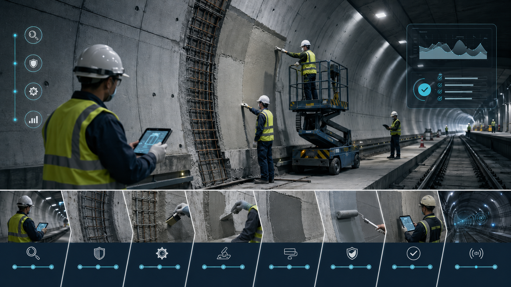
Conceptual controlled rehabilitation workflow showing material preparation, field execution, protective treatment, verification, handover and lifecycle monitoring.
CCL-03

Rehabilitation, protection and controlled delivery

Controlled delivery connects preparation, intervention, verification, handover and monitoring.

Conceptual illustrations. Representative platforms, workflows and technology families remain subject to project-specific evidence, engineering review, safety requirements and owner acceptance.

Direct completed-project experience

Transferable field execution,
clearly separated from specialist capability.

Representative non-rail examples demonstrate direct experience in localized concrete restoration, substrate preparation, execution and documented follow-up. They do not, by themselves, constitute proof of prior delivery of a complete railway inspection system.

Representative non-rail field example

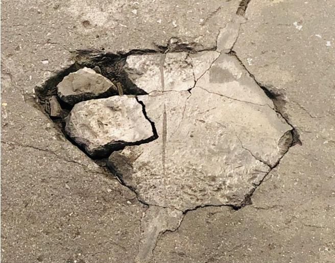
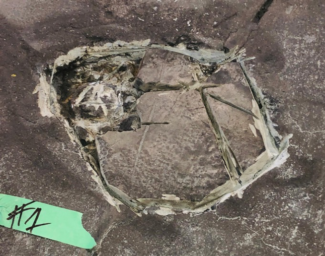
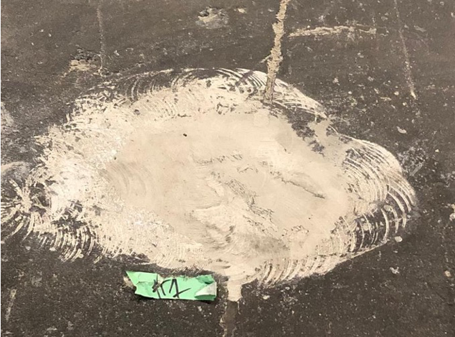
Localized concrete and reinforcement restoration

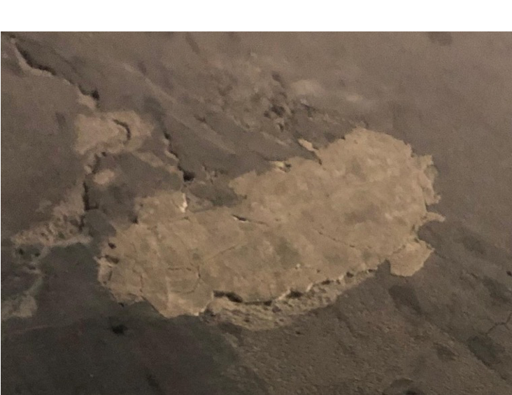
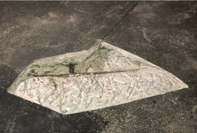
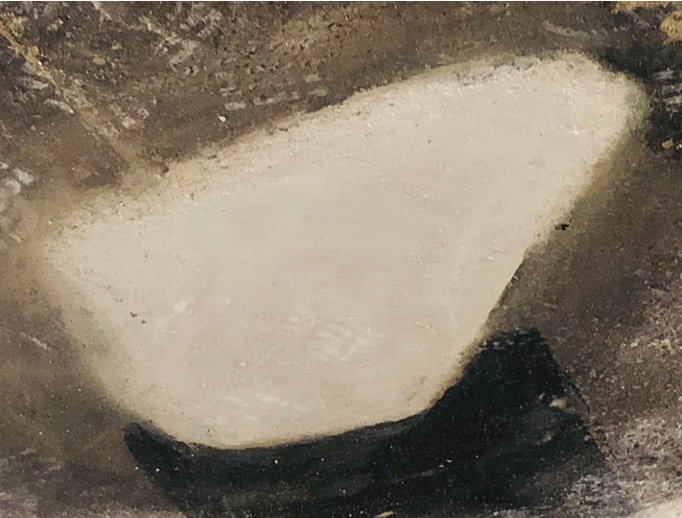
01 Distress02 Prepared03 Reinstated
Condition

Localized concrete deterioration with evidence of prior repair and reinforcement-area distress.

Field role

Condition review, removal of unsound material, mechanical preparation, reinforcement-area treatment and localized reinstatement.

Demonstrated capability

Distressed-concrete preparation, localized restoration, repair execution and constructability.

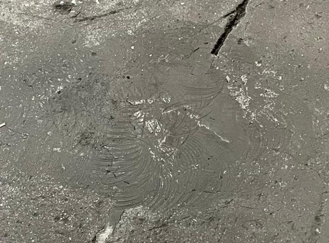
Representative non-rail field example

Heavy-traffic industrial floor restoration with documented follow-up

01 Distress02 Prepared03 Reinstated04 Follow-up
Condition

Localized concrete deterioration in a surface exposed to repeated heavy-equipment traffic.

Field role

Inspection, mechanical preparation, localized reinstatement and return-to-service coordination.

Demonstrated capability

High-traffic repair execution, operational constructability and documented follow-up after continued service.

One coordinated pathway: proven field execution is connected to project-specific inspection technology, specialist validation, engineering, local delivery and accountable client decisions.

Infrastructure environments

Built for complex, operational assets.

The framework is adaptable across civil and structural environments while preserving asset-specific access, safety, materials and acceptance requirements.

A01

Underground, tunnel and track assets

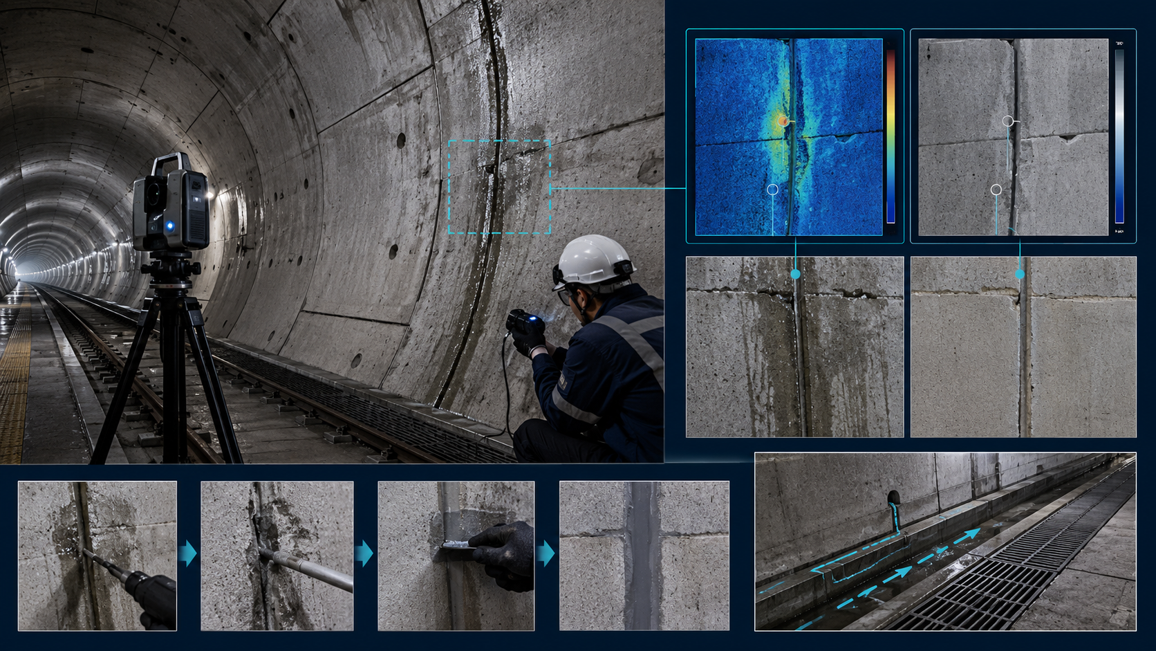
Linings, joints, track beds, plinths, walkways, handrails, cladding, drainage, fixings and loose, missing or displaced elements across cut-and-cover, bored and NATM tunnel environments.

A02

Stations and depots

Concrete, façades, roof canopies, high ceilings, high walls, large floor and ceiling areas, platforms and architectural or structural components in underground and above-ground stations and depots.

A03

Bridges and viaducts

Superstructure, substructure, bearings, supports, box-girder zones, foundations, soil and ground conditions around foundations, erosion and scour.

A04

Concrete and embedded systems

Cracks, spalls, reinforcement, interfaces, voids, delamination, reinstatement and protective functions.

A05

Structural steel, anchors and fixings

Connections, bolts, welds, section condition, fatigue-sensitive details and protective systems.

A06

Water-management interfaces

Visible seepage, joints, membranes, waterstops, drainage and possible migration pathways—investigated before intervention.

Representative—not exhaustive: these asset families establish a practical starting architecture. The detailed scope expands when construction, material, operational and stewardship evidence identifies additional systems, interfaces or risks.

Representative asset pathways

From a recurring condition
to the next defensible decision.

Each pathway illustrates how routine screening, targeted validation and functional intervention logic can be adapted to a representative metro asset. The pathways are examples, not final prescriptions.

P02

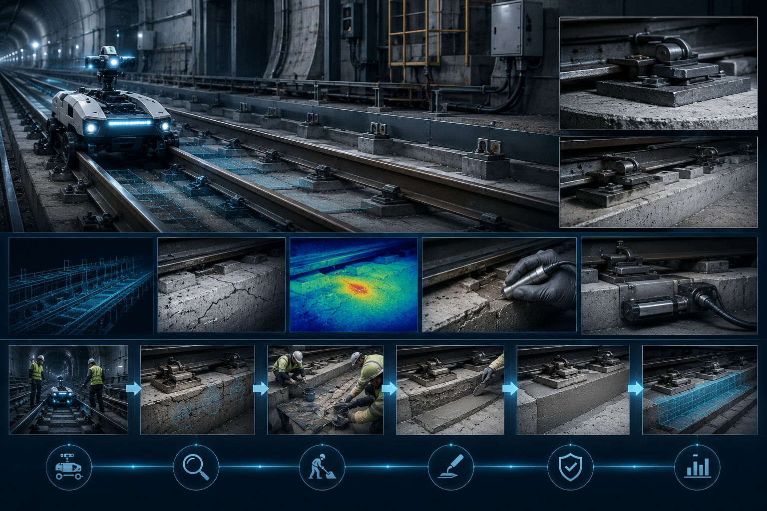
Track bed, plinth and trackside elements

Conceptual track-bed, plinth and trackside pathway showing repeatable rail-compatible screening, targeted validation, localized repair and verification.

Representative conditions include visible cracks, possible microfissuring, detached prior repairs, spalls, geometric change and loose, missing or displaced elements.

Routine screeningRail-compatible repeatable imaging, LiDAR or profiling, route geolocation and automated comparison of track-bed, walkway, cladding, fixing and handrail conditions.
Targeted validationClose measurement, sounding or targeted concrete NDT, interface review and vibration, displacement or strain characterization where the decision requires it.
Decision outputSeparate localized surface deterioration from active movement, interface loss, dynamic influence or a condition requiring structural escalation.
Functional pathwayLocalized reinstatement, interface treatment, movement- or cyclic-load-tolerant rehabilitation, fixing restoration, structural review or monitoring.
P03

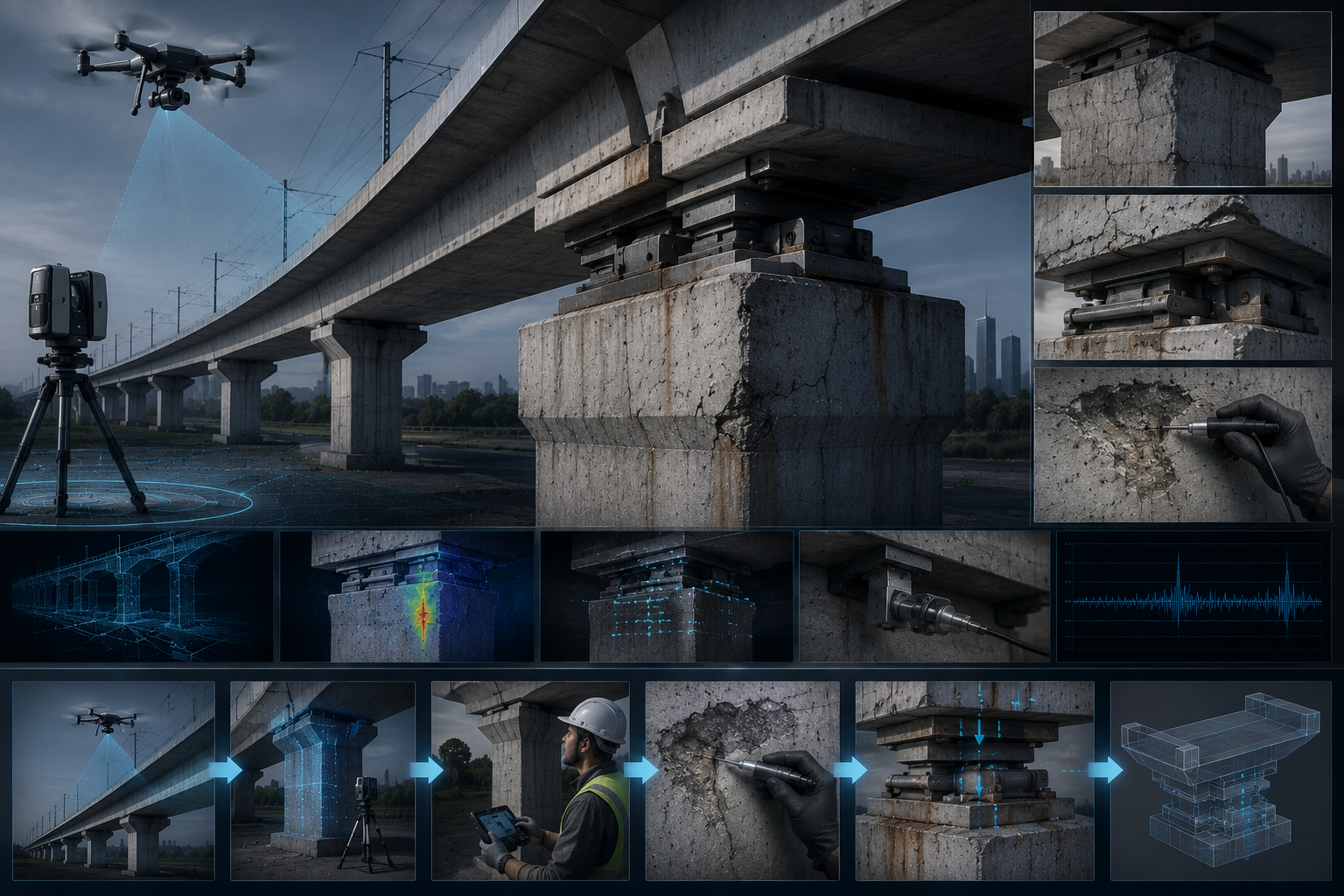
Viaduct bearing pedestal and support zones

Conceptual viaduct bearing pedestal and support-zone pathway showing remote capture, geometry review, close inspection, monitoring and support-system evaluation.

Representative conditions include cracking, spalling, corrosion staining, bearing-zone distress, apparent displacement or deterioration at load-transfer interfaces.

Routine screeningDrone or terrestrial imaging, photogrammetry, LiDAR/survey comparison and targeted repeat views of bearings, pedestals, supports and adjacent concrete.
Targeted validationTouching-distance inspection, crack and geometry measurement, reinforcement/corrosion assessment, movement monitoring and structural review.
Decision outputDetermine whether the concern is localized deterioration, active corrosion, bearing/support movement, interface failure or a load-path issue.
Functional pathwayConcrete reinstatement, reinforcement protection, bearing/support correction, structural repair or strengthening, verification and monitoring.
P04

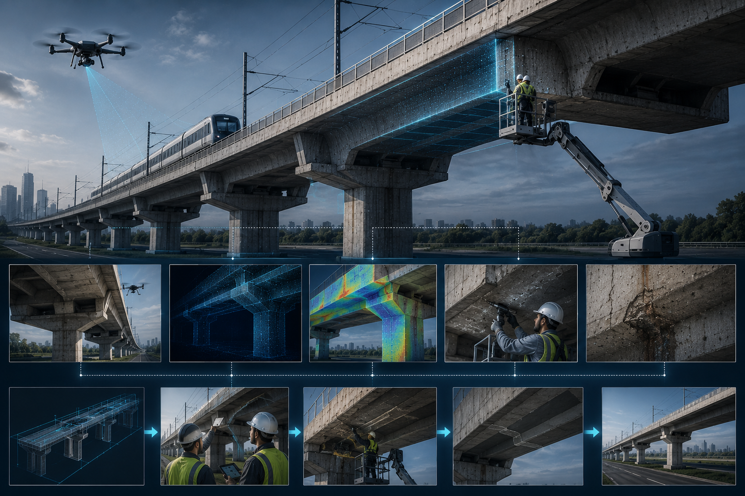
Box girders and viaduct superstructure

Conceptual box-girder and viaduct-superstructure pathway showing drone and terrestrial capture, geometric comparison, thermography, close inspection and controlled intervention.

Representative conditions include cracking, delamination indicators, drainage staining, localized concrete loss, internal-access concerns and steel or connection anomalies.

Routine screeningOutdoor drone imaging, photogrammetry, LiDAR, thermal screening where suitable and repeat geometric or condition comparison.
Targeted validationClose-access concrete NDT, interior inspection where authorized, corrosion assessment, steel NDT and structural interpretation.
Decision outputPrioritize surface maintenance, internal investigation, corrosion control, drainage correction or structural assessment according to evidence.
Functional pathwayDrainage restoration, localized concrete or steel rehabilitation, protective systems, structural intervention and monitored acceptance.
P05

Structural steel, anchors and station canopies

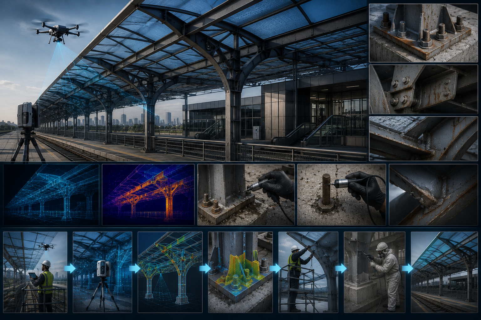
Conceptual structural-steel, anchor and station-canopy pathway showing remote screening, geometry and thermal review, connection inspection, protection and verification.

Representative conditions include coating failure, corrosion, loose or missing fasteners, weld indications, section loss, deformation and fatigue-sensitive details.

Routine screeningDrone or telescopic imaging, photogrammetry, repeat detail capture and automated comparison of connections, coatings and geometry.
Targeted validationTouching-distance inspection, torque or geometry checks where applicable, thickness measurement and specialist MT, PT, PAUT, TOFD or ACFM as justified.
Decision outputSeparate coating maintenance from active corrosion, connection distress, fatigue concern or structural-capacity review.
Functional pathwaySurface preparation and protection, fixing/connection restoration, weld repair under approved procedure, strengthening, replacement or monitoring.
P06

Stations, depots and high-level interiors

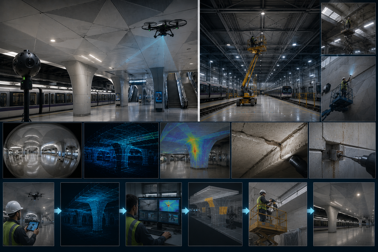
Conceptual station, depot and high-level interior pathway showing 360 imaging, controlled high-reach access, geometric mapping, thermography, close inspection and reinstatement.

Representative conditions include ceiling or wall deterioration, façade and canopy defects, large-area finish failure, water-related indications and difficult-access components.

Routine screening360° imaging, telescopic or remote capture, permitted indoor/outdoor drone use, thermography, façade mapping and repeat large-area comparison.
Targeted validationQualified close access, material identification, adhesion or delamination investigation, moisture/source review and specialist structural or façade assessment.
Decision outputPrioritize safe access, localized maintenance, envelope investigation, structural escalation or monitoring.
Functional pathwayLocalized reinstatement, compatible coating/membrane work, façade or canopy intervention, controlled access planning and documented handover.
P07

Foundations, soil, erosion and scour

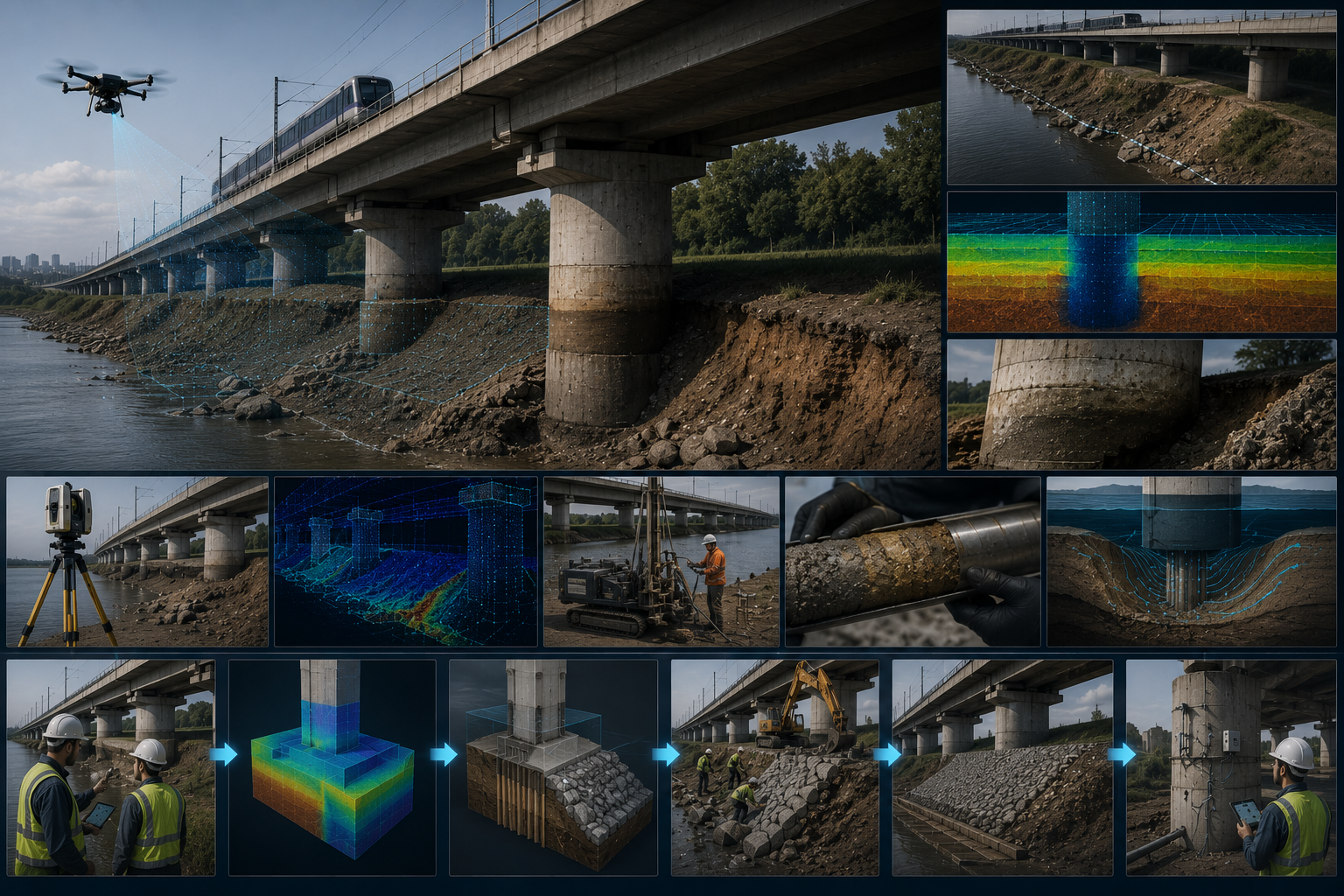
Conceptual foundation, soil, erosion and scour pathway showing survey, ground investigation, water-path analysis, stabilization, protection and monitoring.

Representative conditions include visible erosion, scour, settlement indicators, drainage concentration, exposed foundation interfaces or changes around viaduct supports.

Routine screeningDrone/photogrammetric survey, repeat ground imagery, geometric comparison, drainage observation and fixed monitoring where justified.
Targeted validationEngineering survey, geotechnical investigation, hydrological or drainage review, ground instrumentation and foundation assessment.
Decision outputDetermine whether the condition is superficial, progressive, drainage-driven, geotechnical, hydraulic or structurally significant.
Functional pathwayDrainage and erosion control, ground stabilization, scour protection, foundation intervention, monitoring or structural escalation.

Conceptual illustrations. These pathways show representative investigation and functional intervention logic; final mechanisms, methods and acceptance criteria remain project-specific.

Coupled-mechanism principle: material, structural, water, ground, thermal, operational and dynamic variables should not be treated as isolated subjects when evidence indicates that their interaction may influence the condition or the reliability of the diagnostic result.

Inspection to repair

From condition evidence to standards-compliant repair and verified lifecycle value.

Inspection is not the endpoint. Validated condition information must lead through functional repair definition, controlled execution, acceptance, conditional warranty and monitoring.

01Screening
02Physical validation
03Diagnostic conclusion
04Repair-function definition
05Approved method and ITP
06Implementation and QA/QC
07Acceptance and conditional warranty
08Monitoring and lifecycle integration

Representative repair functions

  • Drainage and water-path correction
  • Moving-joint and interface treatment
  • Concrete reinstatement and reinforcement protection
  • Corrosion protection and coating renewal
  • Securing or replacing fixings and components
  • Erosion control, stabilization or structural escalation where required

The selected function depends on the validated condition, mechanism, substrate, movement, exposure, access and performance requirement.

Standards, QA/QC and acceptance

  • Applicable standards, recognized best practice and owner requirements
  • Manufacturer and main-contractor recommendations
  • Approved method statement and Inspection and Test Plan
  • Substrate, preparation and environmental checks
  • Hold points and documented acceptance criteria
  • Post-repair verification and monitoring

Execution is controlled, documented and verified—not treated as a product-only decision.

Warranty and lifecycle value

Where a repair warranty is offered, its scope and duration remain conditional on the approved system, substrate and environmental conditions, preparation, installation responsibilities, acceptance requirements, monitoring obligations and agreed exclusions.

  • Service-life extension
  • Reduced recurrence and repeat intervention
  • Reduced waste and unnecessary access
  • Optimal Resource Allocation
  • Reduced operational disruption
  • Avoided premature replacement

Documented material attributes: where supported by controlled TDS, SDS and technical evidence, applicable repair materials may be described as 100% solids, fully reactive and solvent-free. Environmental claims remain evidence-based, system-specific and project-specific.

Professional boundary: repair selection remains project-specific. No single material, product or method is represented as a universal solution. Qualified professionals and the owner approval process retain responsibility for final decisions.

Technology architecture

The platform, payload and analytic method are selected by the decision they must support.

Candidate technologies form an evaluation portfolio—not a purchasing list. Digital capture and AI can improve coverage, repeatability and prioritization, but they remain within a controlled workflow that requires engineering review, physical validation and escalation to specialist inspection where the decision demands it.

Rail-compatible mobile capture Calibrated RGB and 360° imaging LiDAR and laser profiling Radiometric thermography Concrete and corrosion NDT Vibration and deformation sensing Drainage and water-path investigation Outdoor drone inspection AI-assisted screening Portable baseline systems Installed monitoring where justified Predictive-maintenance support

Suitability depends on asset geometry, construction materials, reinforcement, layering, moisture, environmental noise, calibration, reference data, railway access and the decision consequence. Portable systems may establish the baseline, mobile systems may repeat routine routes, and installed sensors may support longer-term monitoring where the risk and lifecycle case justify them.

Operational and regulatory readiness: technology availability alone does not establish deployment readiness. Drone use requires competent authorized pilots and the applicable GACA, site, security, railway and client permissions. Equipment, procedures, data controls and owner acceptance remain part of readiness.

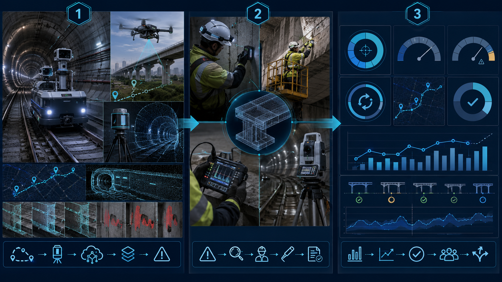
01Geolocated captureRepeatable mobile, fixed or specialist acquisition
02AI-assisted screeningChange detection, anomaly triage and prioritization
03Accountable reviewEngineer and qualified specialist interpretation
04Targeted validationTouching-distance inspection, NDT and ground truth
Technology by operating environment

Different environments require different platforms, payloads and evidence outputs.

The following families illustrate the practical technology architecture expected by metro operators. They remain candidate combinations until access, materials, geometry, safety, data and decision requirements are confirmed.

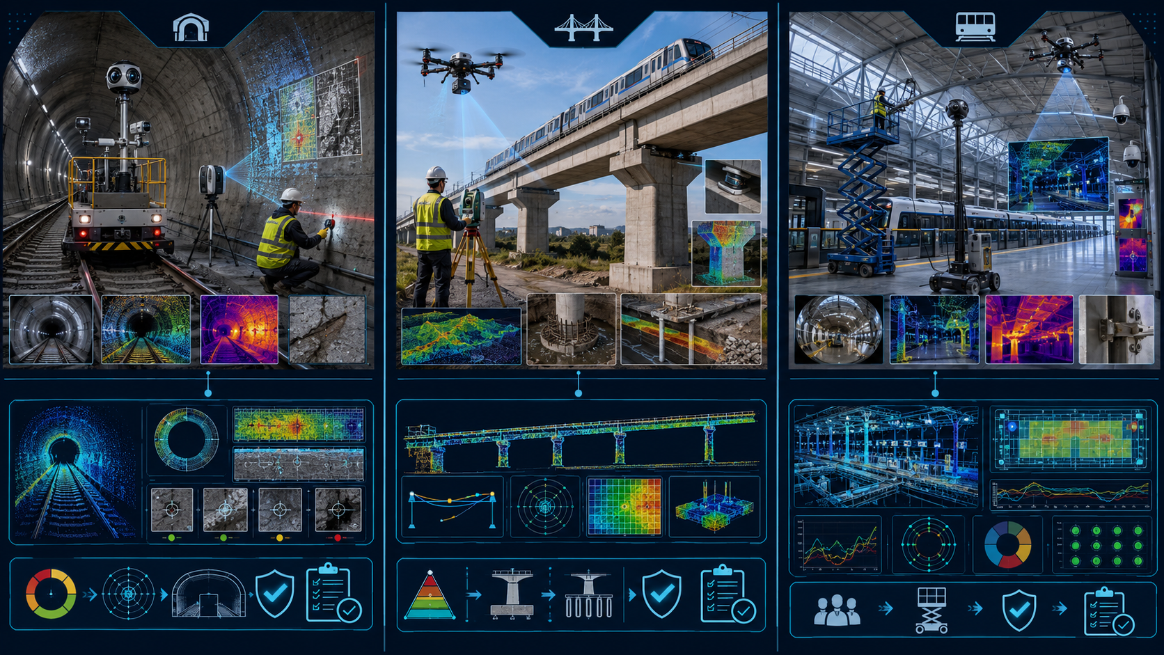
Track and tunnels

Repeatable linear screening with targeted escalation

Rail-compatible mobile platforms, portable systems and specialist tools may be combined according to tunnel type, clearance and possession constraints.

  • RGB/360° imaging for visible condition and loose, missing or displaced elements
  • LiDAR or profiling for geometry, clearance and repeat comparison
  • Thermal/moisture methods where material and environmental conditions support interpretation
  • Targeted concrete, corrosion, drainage, vibration and movement investigation
Decision-support output

Geolocated condition records, change alerts, prioritized anomalies, inspection escalation and evidence for a tunnel-first pilot.

Viaducts, bearings and foundations

Remote access with distinct bearing, pedestal and ground validation

Bearings are functional components; seats, pedestals and support zones are related but distinct inspection subjects. Remote methods can extend external coverage while preserving physical, dimensional and functional inspection where access and the decision require it.

  • Drone imaging and photogrammetry for superstructure, substructure and difficult access
  • LiDAR/survey for geometry, deformation and repeat comparison
  • Touching-distance bearing alignment, displacement, movement, seat and support-zone checks
  • Movement monitoring, steel NDT, corrosion investigation, geotechnical and scour assessment
Decision-support output

Prioritized bearing function, pedestal/support, structural, corrosion, soil, erosion or scour questions and a focused validation plan.

Stations and depots

Large-area and high-level inspection with controlled access

Remote, telescopic, mobile and fixed systems may improve coverage of underground and above-ground stations, façades, canopies and depot assets.

  • 360° and repeat imaging for large floor, ceiling and wall areas
  • Telescopic or permitted drone capture for high-level components
  • Thermography, façade mapping and targeted material investigation
  • Fixed monitoring or change detection for recurring or risk-significant areas
Decision-support output

Asset registers, condition maps, prioritized access, detailed-inspection targets and lifecycle maintenance inputs.

Technology-selection and readiness boundary: this is an evaluation architecture, not a purchasing list. Supplier, model, railway reference, integration, ownership/rental strategy, data-hosting route, competent personnel and approval remain project-specific. Drone deployment also remains subject to applicable GACA, site, security, railway and client permissions.

Technology-by-operating-environment framework separating track and tunnel inspection, outdoor viaduct and foundation inspection, and station or depot inspection with distinct platforms and decision outputs.
Technology combinations change with access, geometry, safety constraints and the decision each environment must support.

Routine inspection operating model

Reduce routine inspection effort without diluting engineering accountability.

The objective is not to replace qualified principal inspection. It is to increase repeatable coverage, identify change earlier and direct specialist resources to the locations and questions that warrant closer investigation.

DETAILED

Targeted touching-distance and specialist inspection

Qualified inspectors, direct measurements, specialist NDT, samples, laboratory work and engineering interpretation focused on selected anomalies and risks.

VALUE

Operational metrics demonstrated through a pilot

Coverage rate, route speed, setup time, operators, possession time, data-processing effort, escalation rate, false-result controls, repeatability and lifecycle cost.

Three-stage metro routine-inspection operating model linking automated screening, targeted specialist validation and measurable operational value.
Routine screening, targeted validation and operational metrics remain connected within one accountable workflow.

Preventive maintenance and lifecycle governance

Existing obligations govern first. Data may support optimization later.

Reduced-manpower screening is intended to strengthen maintenance intelligence—not override manufacturer, contractor, standard, owner, operator or warranty requirements.

01

Compliance hierarchy

Preventive-maintenance inspections remain aligned with applicable manufacturer and main-contractor recommendations, international standards, owner and operator procedures and warranty obligations.

02

Lifecycle intelligence

Commissioning date, manufacturer and model, intended service life, required inspection, maintenance and replacement intervals, condition history and prior interventions form part of the controlled asset record.

03

Optimization boundary

Any optimization of inspection frequency requires validated repeat-condition data, coordination with the operator and client representative, and appropriate authorization.

Lifecycle decision: repeatable evidence may support a documented decision to continue service, monitor, maintain, repair or replace—but does not independently change mandatory intervals or warranty obligations.

What the pilot must demonstrate

Operational value must be measured, not assumed.

A representative pilot should test the complete operating chain, from the current routine process and mandatory maintenance baseline through repeatable capture, engineering review, touching-distance validation, reporting and lifecycle use.

01

Coverage and route speed

Measure the length, area or asset count screened during the available access window.

02

People and setup

Record operators, specialist inputs, setup time, possession demand and safety controls.

03

Geolocation and repeatability

Confirm that the same asset location and viewing geometry can be reliably compared between cycles.

04

Detection integrity

Evaluate data quality, calibration, ground truth and controls for false-positive and false-negative outcomes.

05

Time to accountable report

Measure the interval from acquisition through AI-assisted screening to qualified engineering review.

06

Escalation efficiency

Quantify which anomalies require touching-distance inspection, NDT, sampling or immediate action.

07

Operational compatibility

Verify clearance, isolation, power, communications, cybersecurity, data hosting and railway procedures.

08

Lifecycle and business case

Compare repeatability, disruption, specialist allocation, maintenance obligations, warranty constraints, decision quality and total lifecycle value with current practice.

Manpower objective: the pilot should demonstrate where routine effort can be reduced while preserving qualified principal inspection, engineering accountability and client acceptance.

Digital decision support

Metro Asset Diagnostic Decision Tool

A two-level program-scoping and eligibility framework that connects asset context, construction, material and stewardship genealogy, representative conditions, diagnostic questions, coupled-mechanism considerations, technology suitability, validation gates, functional solution categories and the next controlled phase.

Demonstration prototype. It is not an engineering diagnosis, certified expert system, NDT interpretation, product approval or repair prescription. It deliberately generates an information request when the evidence is insufficient.

Project-specific evolution: under a funded mandate and appropriate engineering governance, the framework could incorporate asset age and lifecycle, manufacturer requirements, mandatory maintenance intervals, warranty restrictions, physical-inspection gates, QA/QC requirements and regulatory permissions. Those functions are not represented as an existing deployed system today.

Open the demonstration

Technology maturity and governance

Maturity, evidence and disclosure are part of the technical decision.

No method is described as client-approved, railway-approved, proven or fit for purpose solely because it exists commercially or appears in a technology catalogue. Each candidate must be reviewed against the required output, evidence, references, environmental constraints, safety and approval pathway.

Proprietary technologies are described by function, relevant properties, maturity and validation gate—without exposing formulation, manufacturing methods or unpublished mechanisms. The categories shown are representative rather than exhaustive and remain subordinate to safety, engineering evidence and owner acceptance.

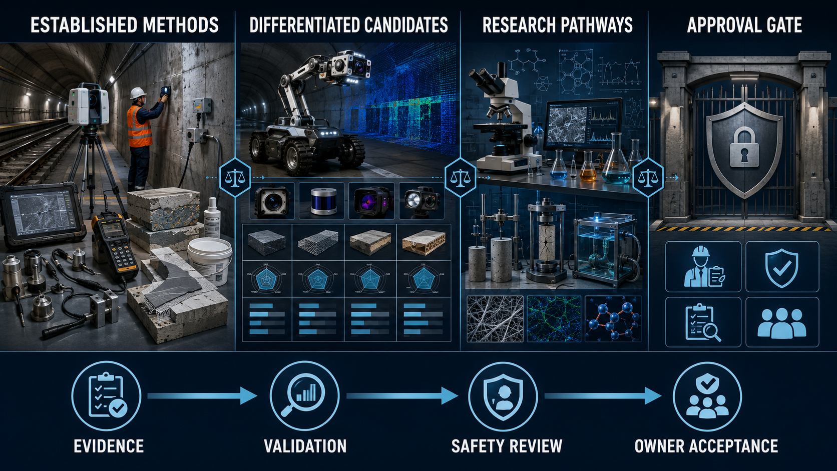
01Established methods — evidence and references reviewed
02Differentiated candidates — project validation required
03Research pathways — controlled disclosure, not deployable
04Approval gate — safety, engineering and owner acceptance
Technology maturity and governance framework showing established methods, differentiated candidates, research pathways and an approval gate.
Technology maturity is governed through evidence, validation, safety review and owner acceptance.

Phased delivery model

A practical path from capability architecture to operational deployment.

The current stage demonstrates the integration model. Project-specific selection, equipment integration, engineering, testing and deployment follow through funded and authorized phases.

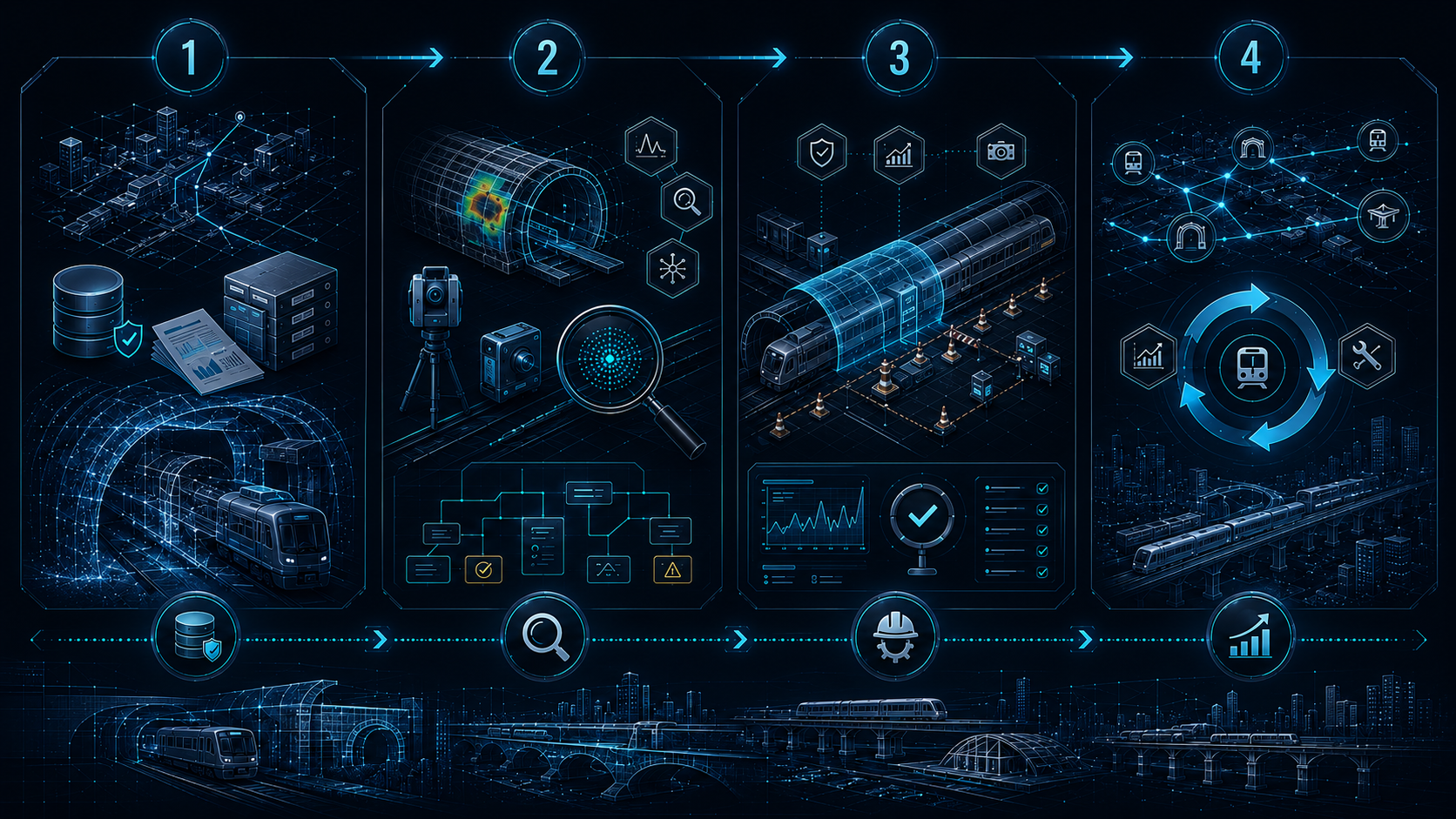
01

Baseline and data package

Segment the assets, obtain construction and material records, define the priority use case, access conditions, required output and evidence gaps.

02

Diagnostic scoping

Define diagnostic questions, platform and payload candidates, confounders, calibration, ground truth, specialist roles and manpower model.

03

Controlled pilot

Test one representative section with repeatable capture, AI-assisted screening, engineering review, touching-distance validation and measurable acceptance criteria.

04

Scale, handover and lifecycle integration

Establish repeatable procedures, digital defect registers, alert rules, monitoring, operator training, knowledge transfer, supervised local capability development, decision rationale, maintenance integration and qualified local delivery.

Saudi delivery readiness: local entity or partner, permits, insurance, qualified personnel, GACA requirements where applicable, railway access, competent-person support, training, knowledge transfer, supervised local capability development and client acceptance remain subject to confirmation.

Commercial boundary: the capability framework can be presented now. Detailed benchmarking, equipment selection, system integration, engineering, formulation work, testing, pilots and deployment require an agreed mandate. No local entity, partner, licence, permit or joint-venture structure is represented as approved.

Four-phase metro infrastructure delivery roadmap from baseline information and diagnostic scoping through a controlled pilot and lifecycle integration.
A phased path from baseline information through diagnostic scoping, controlled pilot and lifecycle integration.

Minimum project data package

Project-specific selection begins with controlled asset information.

Missing information does not prevent a preliminary capability discussion. It does prevent a defensible final selection when the unknown could alter the diagnostic result, material compatibility, access plan or acceptance criteria.

02

Materials, condition, repair and warranty history

Material specifications and genealogy, tests, membranes, waterstops, coatings, original condition records, prior contractors and materials, recurrence or migration, warranty terms and outstanding obligations.

03

Operations, safety, regulatory and approval

Access windows, clearances, isolation, ventilation, railway training, competent-person requirements, equipment restrictions, GACA or indoor-flight permissions where applicable, data ownership and hosting, pilot criteria, budget and authorization route.

Measurable sustainability

Repair-first thinking, better-timed intervention and measurable lifecycle outcomes.

Sustainability is evaluated through infrastructure results—not unsupported labels.

  • Service-life extension and avoided premature replacement
  • Reduced repeat repair, waste and material consumption
  • Reduced routine access demand, possession time and operational disruption
  • Earlier detection and better targeting of specialist resources
  • Documented environmental, safety, durability and acceptance criteria

Material-attribute boundary: where supported by controlled TDS, SDS and technical evidence, applicable repair materials may be described as 100% solids, fully reactive and solvent-free. Environmental claims remain system-specific, project-specific and evidence-based.

About the AegisCrete model

Integration and accountability for complex infrastructure decisions.

AegisCrete is developing one coordinated solution source for evidence-led infrastructure assessment, automated routine screening, diagnostic investigation, functional technology selection, rehabilitation, verification, knowledge transfer and monitoring.

The model brings together direct field execution, materials knowledge, specialist inspection, engineering disciplines, laboratories, digital decision support and qualified delivery partners according to the requirements of each asset and project. Direct completed-project experience is distinguished from specialist or partner-delivered technologies; the model does not assume that every capability is performed internally, already mobilized, railway-approved or owner-approved.

  • Field rehabilitation, constructability and controlled execution
  • Materials, chemistry, provenance and compatibility
  • Qualified engineering, specialist inspection, NDT and laboratories
  • Digital decision support, AI-assisted screening and lifecycle data
  • Railway safety, access planning and accountable verification
  • Training, handover, stewardship continuity and local delivery partners
01Evidence before prescription
02Function before product
03Qualified specialists where required
04Verification before scale
Conceptual AegisCrete coordination model connecting field execution, materials, inspection, engineering, laboratories, digital decision support, verification, training and lifecycle monitoring.
AegisCrete coordinates specialist capabilities and evidence around one traceable infrastructure decision pathway.

Define the first use case

Begin with one representative asset, one decision objective and the evidence available.

A tunnel and track routine-inspection pilot is one practical starting point, but the same controlled architecture can be adapted to viaducts, stations, depots, concrete systems, structural steel, drainage and water-management interfaces. Project-specific equipment, engineering, delivery structure and acceptance criteria are developed from the controlled data package and agreed mandate.

01

Representative asset

Identify the environment, section, structure or system to be examined.

02

Decision objective

Define the operational or technical question the project must answer.

03

Available evidence

Share relevant records, imagery, history, access constraints and known gaps.